Viewing as
Teacher view: planning notes, the answers to every question, and the teacher copies of the files.
Physics · Electricity
Resistors and I–V characteristics
Explain the I–V characteristics of a resistor, filament lamp and diode, and the behaviour of thermistors and LDRs, including Required Practical 4.
Teacher resources
The teacher copies: slides with the questions built in, the answers, and anything else attached to this lesson for whoever is teaching it.
- Resistors and IV characteristics - Teacher Slides.pptx Teacher The lesson slides with the teacher's notes on each slide, and every question and mark scheme built in. Built from the lesson script on 30 September 2026. View
- Resistors and IV characteristics - Teacher Notes.docx Teacher The complete notes with the teacher's notes and every model answer in full. Built from the lesson script on 30 September 2026. View
Student handouts
The same files the students see, to print or hand out.
- Resistors and IV characteristics.pptx Built from the lesson script on 30 September 2026. View
- Resistors and IV characteristics - Completed Notes.docx The full notes for the lesson, to revise from. Built from the lesson script on 30 September 2026. View
- Resistors and IV characteristics - Exam Questions.docx Built from the lesson script on 30 September 2026. View
Warm-up
Answer each one, then check.
-
1
What is an ohmic conductor?
Show answerHide answer
A conductor with constant resistance at constant temperature
-
2
What does I–V stand for?
Show answerHide answer
Current against potential difference
-
3
What is a straight line graph through the origin?
Show answerHide answer
Directly proportional
-
4
What happens to a metal when its temperature rises?
Show answerHide answer
Its resistance rises
-
5
What does LDR stand for?
Show answerHide answer
Light-dependent resistor
Learning Objectives
- 1Describe the I–V graphs of a resistor, filament lamp and diode.
- 2Explain the changes in resistance of a filament lamp, diode, thermistor and LDR.
- 3Describe how to investigate I–V characteristics (Required Practical 4).
- 4Use graphs to say whether a component is linear or non-linear.
I–V CHARACTERISTICS
The current through an ohmic conductor at constant temperature is directly proportional to the potential difference across it, so its resistance is constant.
The resistance of a filament lamp, diode, thermistor and LDR is not constant.
I–V Graphs
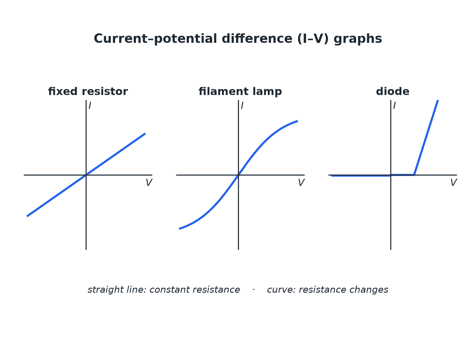
Straight line: constant resistance. Curve: changing resistance.
Thermistor and LDR
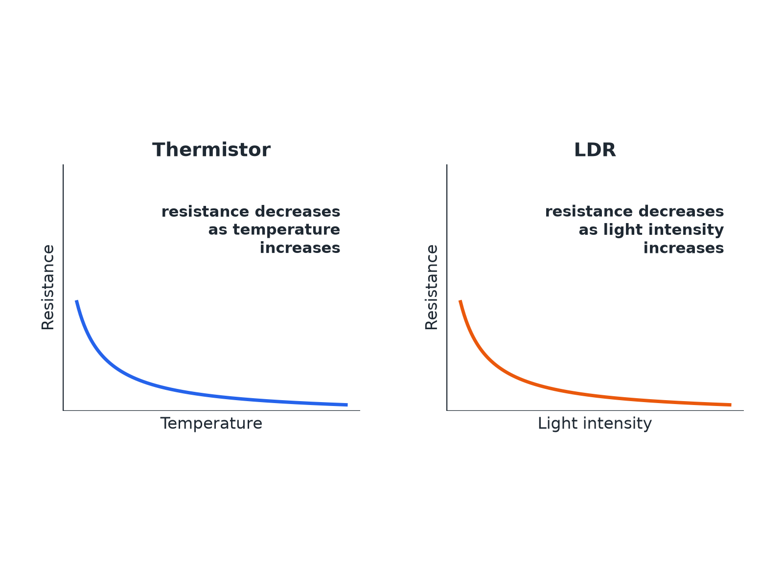
Both fall as the quantity increases.
Required Practical 4: I–V Circuit
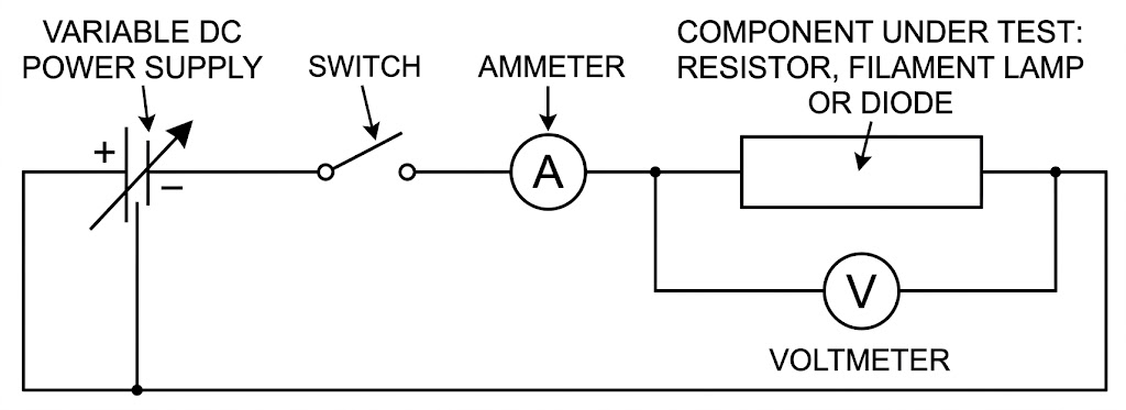
Vary the pd and measure the current each time.
Component Behaviour
Learn each description.
-
Fixed resistor
Resistance: Constant at constant temperature. Graph or behaviour: Straight line through the origin
-
Filament lamp
Resistance: Increases as the filament gets hotter. Graph or behaviour: Curve that flattens; gradient decreases
-
Diode
Resistance: Very high in the reverse direction. Graph or behaviour: Current flows in one direction only
-
Thermistor
Resistance: Decreases as temperature increases. Graph or behaviour: Used in thermostats and temperature sensors
-
LDR
Resistance: Decreases as light intensity increases. Graph or behaviour: Used in automatic lights
Required Practical 4: Method
Find the I–V characteristic of a component.
-
1
Set up
Connect the component in series with the ammeter and variable resistor, and the voltmeter across the component.
-
2
Vary
Change the variable resistor to get different pds.
-
3
Record
For each setting record V and I.
-
4
Reverse
Swap the connections and repeat to get negative values (not for a diode with a protective resistor).
-
5
Plot
Draw current against pd and draw a smooth line.
-
6
Repeat
For the filament lamp and the diode.
Resistance of a Filament Lamp
The current through a filament lamp is 0.34 A at 2.0 V and 0.62 A at 6.0 V. Calculate the resistance at each pd and explain the difference.
Show the solutionHide the solution
- 1 At 2.0 V \(R = 2.0 \div 0.34 = 5.9\ \Omega\)
- 2 At 6.0 V \(R = 6.0 \div 0.62 = 9.7\ \Omega\)
- 3 Explain At the higher pd the current is greater, so the filament is hotter and its resistance is higher
Answer5.9 Ω and 9.7 Ω; the resistance increases as the filament gets hotter.
Uses in Circuits
Applications you need to know.
-
Thermistor
In a thermostat: as the temperature rises the resistance falls, changing the pd across it to switch heating off.
-
LDR
In automatic lights: as it gets dark the resistance rises, which switches the light on.
-
Diode
Allows current in one direction only, protecting circuits from being connected the wrong way round.
Match the Graph
Match each component to its I–V graph description: resistor, filament lamp, diode. (1) Curve that flattens as pd increases. (2) Straight line through the origin. (3) Almost no current one way, then a rapid increase the other way.
1. Look at the shape.
2. Explain the resistance change.
A good answer shows: Resistor: (2). Filament lamp: (1). Diode: (3).
Can I...?
- 1Draw and describe the I–V graph of a resistor.
- 2Describe the I–V graph of a filament lamp.
- 3Describe the I–V graph of a diode.
- 4Explain why a filament lamp's resistance increases.
- 5Describe how a thermistor behaves.
- 6Describe how an LDR behaves.
- 7Describe Required Practical 4.
- 8Give one use each of a thermistor and an LDR.
Summary & Exam Focus
- Resistor: constant resistance, straight line through the origin.
- Filament lamp: resistance increases with temperature.
- Diode: current in one direction only.
- Thermistor and LDR resistances decrease as temperature or light increases.
Exam focus
Explain why the resistance of a filament lamp increases as the current increases. (3 marks) (3 marks)
Say the filament gets hotter and link it to resistance.
Key terms
The vocabulary this lesson expects you to use. Each one is linked from the first place it appears above.
- Ohmic conductor
- A conductor whose resistance is constant at constant temperature.
- Filament lamp
- A lamp with a thin wire that gets hot and glows.
- Diode
- A component that lets current flow in one direction only.
- Thermistor
- A resistor whose resistance decreases when the temperature increases.
- LDR
- A resistor whose resistance decreases when the light intensity increases.
- Linear
- Following a straight line graph.
Questions and answers
11 questions set on this lesson, with the mark schemes and model answers open.
Name the component whose I–V characteristic shows current flowing in one direction only, and the component whose resistance decreases as the temperature increases. Then state what happens to the resistance of an LDR in bright light.
Mark scheme — 3 marks available
- Diode — 1 mark
- Thermistor — 1 mark
- LDR resistance decreases — 1 mark
Model answer
A diode; a thermistor; the resistance of an LDR decreases in bright light.
The graph shows the I–V characteristic of a filament lamp. (a) Calculate the resistance of the lamp when the potential difference is 6.0 V. (b) The resistance at 2.0 V is 5.9 Ω. Explain why the resistance at 6.0 V is different.
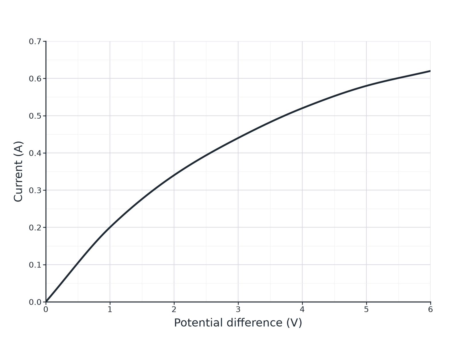
Mark scheme — 4 marks available
- Reads 0.62 A — 1 mark
- 9.7 Ω — 1 mark
- Higher current means higher temperature — 1 mark
- Resistance increases with temperature — 1 mark
Model answer
(a) At 6.0 V the current is 0.62 A. \(R = 6.0 \div 0.62 = 9.7\ \Omega\). (b) At 6.0 V the current is greater so the filament is hotter, and the resistance of the filament increases with temperature.
A thermistor is used in a circuit to control a heating system. Explain how the resistance of the thermistor changes as the room warms up.
Mark scheme — 3 marks available
- Resistance decreases as temperature increases — 1 mark
- Current or potential difference changes in the circuit — 1 mark
- Used to switch the heating off — 1 mark
Model answer
As the temperature increases the resistance of the thermistor decreases, so the current through it increases and the potential difference across it changes; this is used to switch the heating off.
Describe how you would investigate the relationship between the current through a filament lamp and the potential difference across it. Include a circuit diagram description, the readings to take and how you would present and use the results.
Mark scheme — 6 marks available
- Level 3 (5 to 6 marks): a correct circuit (ammeter in series, voltmeter across the lamp, variable resistor or supply), a range of pd values and matching currents, a graph of I against V and a description of its shape or the changing gradient — 5 to 6 marks
- Level 2 (3 to 4 marks): a method with the main apparatus and some readings; the graph is mentioned — 3 to 4 marks
- Level 1 (1 to 2 marks): simple statements about measuring current and pd — 1 to 2 marks
Model answer
See levels-of-response scheme.
A student measures the resistance of a diode. Explain why the resistance is very high when the diode is connected the other way round.
Mark scheme — 2 marks available
- Very high resistance in reverse — 1 mark
- Almost no current flows — 1 mark
Model answer
A diode has a very high resistance in the reverse direction, so almost no current flows.
An automatic outdoor light contains an LDR. Explain how the light switches on when it gets dark.
Mark scheme — 3 marks available
- Resistance of LDR increases in the dark — 1 mark
- Change in pd or current in the circuit — 1 mark
- Circuit switches the light on — 1 mark
Model answer
When it gets dark the resistance of the LDR increases. The pd across the LDR increases (or current decreases), which triggers the circuit that switches the light on.
An ohmic conductor has an I–V graph that is...
Why: Constant resistance gives a straight line.
The resistance of a filament lamp increases because the filament...
Why: Higher temperature means higher resistance.
A diode allows current in...
Why: It has very high resistance in the reverse direction.
As light intensity increases, the resistance of an LDR...
Why: LDR resistance falls in bright light.
As temperature increases, the resistance of a thermistor...
Why: Thermistor resistance falls as it warms.