2.1 Circuit symbols and diagrams
The standard circuit symbols for cells, switches, lamps, resistors, meters and sensors, and how to draw a correct circuit diagram.
Circuit diagrams
Key terms
- Component: any part of an electric circuit, such as a lamp, a resistor or a switch.
- Circuit diagram: a drawing of a circuit that uses standard symbols for the components and straight lines for the wires.
- Series: components connected one after another in a single loop.
- Parallel: components connected on separate branches, side by side.
A circuit diagram shows how the components in a circuit are connected. Every component has its own standard symbol, so a diagram can be read by anyone, anywhere. You need to recognise all of the symbols below and draw them correctly.
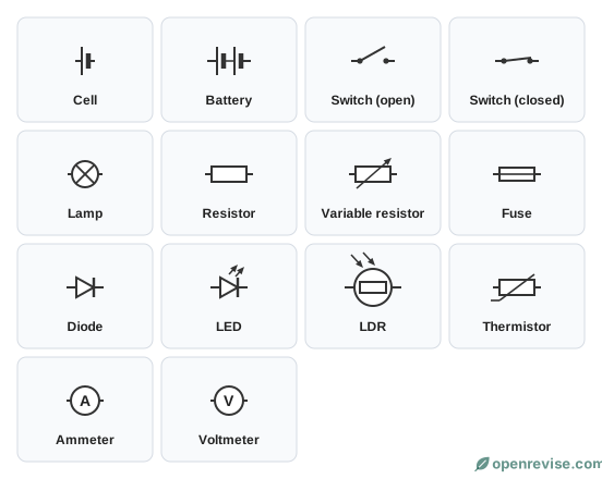
What each component does
| Component | What it does |
|---|---|
| Cell | Supplies the energy that pushes charge round the circuit |
| Battery | Two or more cells joined together |
| Switch | Opens or closes a gap in the circuit to turn it off or on |
| Lamp | Transfers electrical energy to light (and thermal energy) |
| Fixed resistor | Limits the current in a circuit |
| Variable resistor | A resistor whose resistance can be changed, so the current can be changed |
| Fuse | A thin wire that melts if the current gets too big, breaking the circuit |
| Diode | Lets current pass in one direction only |
| LED | A diode that gives out light when current passes through it |
| LDR | Light-dependent resistor: its resistance falls as light gets brighter |
| Thermistor | Its resistance changes with temperature |
| Ammeter | Measures the current in amperes |
| Voltmeter | Measures the potential difference in volts |
Drawing a circuit diagram
- Use a ruler and draw wires as straight lines with sharp corners.
- Draw each symbol neatly, with no gaps between the symbol and the wire.
- Do not draw a component on a corner of the circuit.
- Connect an ammeter in series, in the main loop, so the current goes through it.
- Connect a voltmeter in parallel, on its own branch, across the component it is measuring.
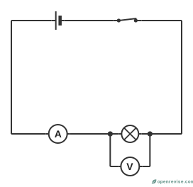
In the circuit above, the same current goes through the cell, the switch, the ammeter and the lamp. The voltmeter is on a separate branch, so it only measures the potential difference across the lamp.
Which way does the current flow?
By convention, conventional current flows from the positive terminal of the cell or battery, round the circuit, to the negative terminal. In the symbol for a cell, the longer, thinner line is the positive terminal and the shorter, thicker line is the negative terminal. A battery is drawn with two or more cells in a row.
Some components only work one way round. The arrow in the symbol for a diode or an LED points in the direction of the conventional current, which is the direction in which they let current through.
Open and closed circuits
A current only flows if there is a complete loop from one terminal of the cell to the other. A circuit that is complete is a closed circuit. A circuit with a gap in it is an open circuit and there is no current. An open switch makes a gap on purpose. A broken wire, a blown fuse, a flat cell or a loose connection can also make a circuit open by accident, which is a common reason why a circuit does not work.
What each component does with the energy
| Component | Energy transfer |
|---|---|
| Cell or battery | Chemical store to electrical |
| Lamp | Electrical to light (and thermal) |
| Resistor | Electrical to thermal |
| Heater | Electrical to thermal |
| Motor | Electrical to kinetic (and thermal) |
| Buzzer | Electrical to sound |
Reading a circuit diagram
When you look at a circuit diagram:
- Find the cell or battery and trace the loop of wire all the way round.
- Decide whether components are on the same path (in series) or on different branches (in parallel).
- Look at any meters. An ammeter must be in the main loop with the component. A voltmeter must be on a branch of its own, across the component.
- Look at the switches. Only the part of the circuit that a switch is part of will be switched off.
Common mistakes when drawing circuits
- leaving gaps between a symbol and the wire;
- drawing wires as curved or freehand lines, instead of straight lines with a ruler;
- putting a component on a corner of the circuit;
- drawing a voltmeter in series or an ammeter in parallel;
- drawing a cell or diode the wrong way round, when the direction matters.
Test yourself on this lesson
9 exam questions · 17 marks · with mark schemes and model answers
Found a mistake?