2.9 Required practical: resistance of wires and combinations
Required practical: investigate how the resistance of a wire depends on its length, and how resistors combine in series and in parallel.
Aim
To investigate the factors that affect the resistance of an electrical circuit: (a) how the length of a wire affects its resistance, and (b) how resistors combine when they are connected in series and in parallel.
Key terms
- Directly proportional: when one quantity doubles, the other doubles too. A graph is a straight line through the origin.
- Independent variable: the variable you change. Here it is the length of the wire.
- Dependent variable: the variable you measure. Here it is the resistance.
Apparatus
- a length of resistance wire taped to a metre ruler
- two crocodile clips
- power supply (d.c.) and switch
- ammeter and voltmeter
- connecting wires
- fixed resistors
Part A: resistance and length of a wire
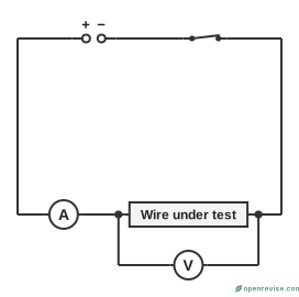
- Connect the circuit as shown, with the ammeter in series and the voltmeter in parallel across the length of wire.
- Fix one clip at the 0 cm mark. Fix the other clip at 20 cm. This is the length of wire in the circuit.
- Close the switch. Record the potential difference and the current, then switch off straight away.
- Calculate the resistance using R = \frac{V}{I}.
- Repeat for lengths of 40, 60, 80 and 100 cm.
- Plot resistance (y-axis) against length (x-axis).
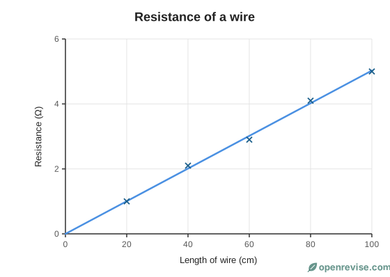
The graph is a straight line through the origin, so the resistance is directly proportional to the length. Doubling the length doubles the resistance. A longer wire has more ions that the electrons can collide with, so it is harder for the charge to flow.
Part B: resistors in series and parallel
- Measure the resistance of two resistors, R_1 and R_2, separately using R = \frac{V}{I}.
- Connect them in series and measure the resistance of the combination.
- Connect them in parallel and measure the resistance of the combination.
- Compare the results with the rules.
| Arrangement | Total resistance |
|---|---|
| Series | The sum, R_1 + R_2 |
| Parallel | Smaller than either resistor on its own |
Precautions and sources of error
- Keep the current small and switch off between readings. A hot wire has a higher resistance, which would spoil the results.
- Use the same wire, with the same thickness, throughout.
- Read the length at the inside edges of the clips, and keep the wire straight.
- Check the meters for zero errors, and repeat each reading to find a mean.
Using the graph to predict resistance
The graph of resistance against length is a straight line through the origin, so its gradient is the resistance of each centimetre of wire.
Example. If the graph shows that 100 cm of the wire has a resistance of 5.0 Ω, the gradient is \frac{5.0}{100} = 0.050 Ω per cm. The resistance of 70 cm of the same wire is then 0.050 \times 70 = 3.5 Ω. You can also use proportion: doubling the length doubles the resistance.
Why does the thickness of a wire matter?
A thicker wire has a lower resistance. A thicker wire has more room for the free electrons to move through, so more electrons can carry charge at the same time, like water flowing through a wide pipe compared with a narrow pipe. If the cross-sectional area of the wire is doubled, the resistance is halved. A longer wire has a higher resistance, because the electrons collide with more ions on their journey. The material matters, too: copper has a very low resistance, whereas nichrome (used in heating elements) has a high resistance.
Example results for combinations of resistors
| Arrangement | Predicted total resistance | Measured total resistance |
|---|---|---|
| In series | 30.0 Ω | 29.8 Ω |
| In parallel | 6.7 Ω | 6.6 Ω |
In series the total resistance is the sum of the resistances. In parallel the total is smaller than the smallest resistance (in this case, smaller than 10 Ω). The measured results are very close to the predictions. (For two resistors in parallel, the predicted value comes from the product divided by the sum: \frac{10 \times 20}{10 + 20} = 6.7 Ω. You do not need to remember this rule, but it can be used to check your results.)
Evaluating the method
- Contact resistance: the crocodile clips add a little resistance of their own. Make sure the clips are clean and make good contact, and take readings for a wide range of lengths so that this small error matters less.
- Heating: if the current flows for a long time, the wire gets hot and its resistance rises. Switch off between readings.
- Measuring the length: a crocodile clip has a thickness, so it is hard to read the length exactly. Read the length at the inside edge of each clip.
- Reliability: repeat each reading and find a mean. Use digital meters to read more precisely.
Comparing the two parts
In Part A you change the length of one wire and find that the resistance changes in proportion. In Part B you change the way components are connected and see how the total resistance changes. Both use the same method for finding resistance: R = \frac{V}{I}.
Test yourself on this lesson
9 exam questions · 19 marks · with mark schemes and model answers
Found a mistake?